 |
|
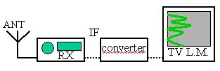
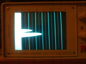
I started testing in WFM mode, since the "IF out" on AR8600 is disabled in all others as a factory default.
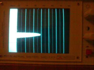
No reference is given on the instrument between bandwidth knob position and frequency range shown on screen,
but a few minutes of trial and error, will yield the setting so that full IF bandwidth is shown occupying
the entire screen. Some attenuation (20dB) had to be selected from the control panel as signals would otherwise
swamp the entire screen.
|
 |
| Then I proceeded performing the "all mode IF out modification". A 0 ohm smd resistor had to be
moved to a nearby track. A very sharp soldering iron is needed and I lost my temper trying to solder it back into
the new position. Eventually I just dropped some tin in its place. Hopefully this won't make a difference. Further
testing needed.
|
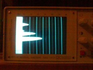
| Related or not, in modes other than WFM a fixed spike appears on the screen. It looks like it's offset from the
center frequency by a few hundred KHz (should check if 10.7MHz +- other LO). At this stage I'm unsure if this is
normal, a side effect of my badly performed modification, a by-product of the receiver-downconverter interaction
or anything else.
At first I found it very annoying, but after a few minutes I wasn't noticing it anymore, using it almost as an
on-screen reference for tuning.
|
 |
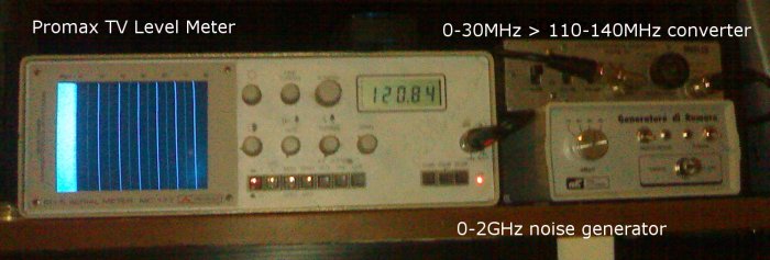
| UPDATE: I eventually bought an RFSpace SDR14 and one of the first tests was to check the
IF out signal. As clearly shown the image below, the rogue signal is 455kHz off the center frequency and clearly
a receiver byproduct. Several other spurious signals can be seen, but AOR clearly warned about this. |
 |
| The same seen on a HP8922M Spectrum Analyzer, this time left of center frequency. |
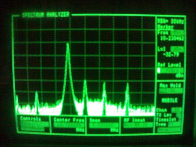 |
Tuning on the analyzer should not be touched further, using the radio knob instead. Spinning the frequency
control will cause the various spikes to move across the screen. I found that once the radio is tuned to the right
frequency for a signal, the corresponding spike disappears.
|
THIS IS AMAZINGLY EFFECTIVE. In a few minutes I discovered a bunch of frequencies who escaped my
previous monitoring efforts. Once tuned to your center frequency, you'll quickly be able to map which spikes
match known channels within the bandwidth. All the rest are your new finds.
Data only channels often show some trembling of the spike's edge.
|
  |
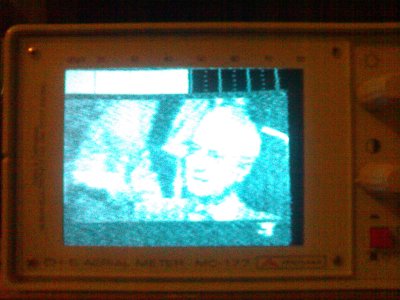
| It didn't occur to me, but the TV display function may come handy to monitor video signals throughout the entire
spectrum, providing a function similar to the Icom R3. I shall try the 2.4GHz band one of these days.
|
 |